Fluorescent Light Wiring Diagram | Tube Light Circuit this is about how to wiring fluorescent light and "how a Fluorescent Tube Light works"..Electronic Circuit Diagram . Free electronic circuit design, schematic diagram, circuit diagram, circuit design, video tutorial.AUTO CAR WIRING DIAGRAM BASIC CIRCUIT FOR INSTALLATION RELAY CONNECTION SPOT LIGHT FOG LAMP INSTALLATION Automotive wiring diagrams basic symbols .Working of contactor A simple circuit diagram Either of the Two Start Buttons will close the contactor, Either of the STOP buttons will open the Contactor..A basic led circuit is nothing more than simple things which are a battery, a current limiting resistor and an LED. A current limiting resistor is used to provide .The following diagram is the basic design diagram of inverter circuit. The circuit will convert V DC to V AC. This basic inverter circuit can handle up to .USB sound card. Description. Designing and building a USB sound card is no longer a head ache because we have got the PCM integrated circuit from Texas Instruments..Circuit Diagram. A circuit diagram is a visual display of an electrical circuit using either basic images of parts or industry standard symbols..A recent look at some of the budget priced HF transceivers revealed that they were missing a VOX. Although most of these budget priced transceivers performed .Free Electronic Circuits with Circuit Diagram, schematics and Component description. Latest hobby electronic circuits and new projects with schematics and circuit .
Led Circuit Schematic
A Simple Schematic Diagram
Diagram Of Electric Circuit Ireleastcircuit Diagrambasic Electrical Circuit Diagrams

Schematic Diagram
Image Jpg
The Conductor Is Used To Connect The Positive Side Of The Power Source To The Load Which Is Then Connected Back To The Negative Side Of The Power Source To

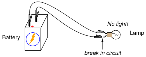
To The Lamp Is More Important To Circuit Operation Than The Other Wire Providing A Return Path For Electrons Back To The Battery This Is Not True
Led Circuit Schematic
A Simple Schematic Diagram
Image Result For Basic Circuit Diagram
A proud thing can help Readers to gain information regarding Basic Circuit Diagram, if you have any shortcomings in the picture of Basic Circuit Diagram so you can ask for help by finding what you want in search box. If this article helps, We are very thankful if you share this article to others.


0 Response to "Basic Circuit Diagram"
Post a Comment