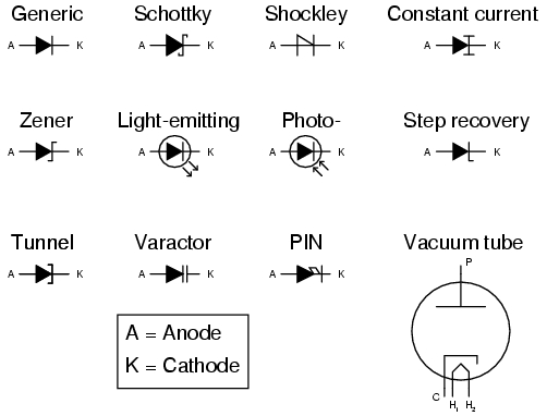
An electronic symbol is a pictogram used to represent various electrical and electronic devices such as wires, batteries, resistors, and transistors in a schematic .Capacitor Symbols. Capacitor schematic symbols capacitor, polarized capacitor, variable capacitor. Table of capacitor symbols.Electrical symbols electronic circuit symbols of schematic diagram resistor, capacitor, inductor, relay, switch, wire, ground, diode, LED, transistor, power .Xilinx Orcad schematic symbol and PCB layout footprint libraries of Virtex Spartan FPGA and CPLD components..An overview of the most used schematic symbols in electronic circuits. These symbols are essential to be able to read schematic diagrams..The standard electrical symbols are smart, industrial standard and vector based for electrical schematic diagrams. Most of electrical symbols can change their .Using the reference is very simple. All you need to do is move your mouse over the symbol you want information about and click. Note that when you move your mouse . Schematic Diagrams and Symbols Peter Mathys ECEN Circuits and Devices A circuit is a collection of interconnected electrical devices such that .Electrical Schematic Symbols Electrical circuit schematic symbols are graphical sign, that is used to design electronic, electrical circuit schematic diagram..Circuit symbols are used in circuit schematic diagrams which show how a circuit is connected together electrically. The standard circuit symbols are important for .

Easy To Read Schematics All Electronics Symbols A Very Useful Thread To Learn About Electronics And Mobile Schematics For Those Who Love Their Work

Symbols This Electrical Schematic Symbols Page Was Created To Aid And Assist

Click On Image To Enlarge Circuit Schematic Symbols Schematic Symbols Im Electronic

Electronic Symbol

Electrical Schematic Symbols Electrical Circuit Schematic Symbols Are Graphical Sign That Is Used To Design Electronic Electrical Cir

Schematic Component Overview

Chapter Circuit Schematic Symbols

Schematic Component Overview

Electrical Schematic Symbols Electrical Circuit Schematic Symbols Are Graphical Sign That Is Used To Design Electronic Electrical Cir

Image Result For Schematic Symbols In Electronics
We are very happy to help Readers to gain information regarding Schematic Symbols In Electronics, if you found the picture vagueness in Schematic Symbols In Electronics so you can look for it using the search box. If this article helps, We are very pleased if you share this post to others.


0 Response to "Schematic Symbols In Electronics"
Post a Comment